
Relay Wiring Diagram
"The module performs exactly as it should, the relay clicks but nothing happens"
Using a Velleman VM141 timer module as our example we will show you how to connect power to the on board relay. All of our Cebek or Velleman modules which use a relay have 'Volt free Contacts'. This means the load connected to the relay requires its own power supply. You could use the same supply as the module but more often than not you will use a separate power supply. (Figure 1) Shows the relay connected to a separate supply. We have connected the positive supply to the common (COM) terminal on the relay. When the relay is energised the contacts will close and complete the circuit. If you wanted to disconnect a load when the relay is energised use the the Normally Closed (NC) contact. If you follow this advice you should have no problem switching on and off any device connected to the relay. See our full range of Electronic Modules | 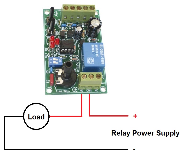 Figure 1 |
ESR Electronic Components Ltd Cullercoats Tyne and Wear NE30 4PQ